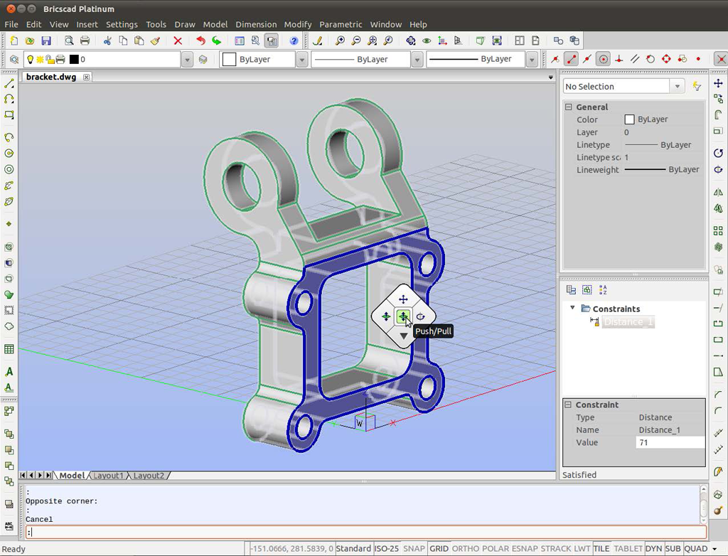

QUICK SUMMARY OF THE BRICSCAD QUAD VARIABLES Understanding how the BricsCAD Quad worksĬustomizing the commands and groups displayed by the BricsCAD Quad.The following topics are covered in this post: The content of the Quad's interface is changed through the Customize dialog box, and that is the subject of this post. Select a 3D solid and solid editing commands appear. The Quad also uses entity recognition to determine which commands are suitable at the moment, especially when it comes to editing. This means that commands specific to BricsCAD Mechanical appear in the Mechanical workspace, BricsCAD BIM commands in the BIM workspace, and so on. BricsCAD uses workspaces to determine which groups of commands are displayed by the Quad, just as with the Ribbon. The trend in CAD user interface design is to move more of the action to the cursor, and so Bricsys ® developed the Quad interface to do just that: it allows us to select commands very near to the cursor. Import and export 3D models from DAE, 3DS, FBX, and OBJ files to AutoCAD, and export them and other 3D entities such as 3D solids, regions, meshes or polymeshes to Google Earth.In this post, you learn about the BricsCAD ® Quad, what does it, how you use it and how can you customize it in BricsCAD.Terrain mesh editing commands to insert, delete, move, adjust elevation, flatten vertices, and invert, delete, or cut triangles.ģD entities contained in regular or nested blocks can also be exported.Break lines can be inserted to refine the terrain configuration. The mesh can be smoothed and adjusted to a control mesh or control points. Import terrain meshesfrom LiDAR and DEM files (GeoTIFF, DEM, HGT, E00, MEM, CAT.DDF), specifying mesh properties and refinement options and other processing parameters, with the option to process the entire file or to select the area to process.Export terrain mesh to a text XYZ or GeoTIFF file.Terrain Mesh Explorer, to organize your projects and have access to mesh importing, editing and visualization commands.By right-clicking on a node, a context menu will be displayed to select commands according to the node selected. Display profile sections from selected terrain meshes by defining a cutting line. You can adjust the vertical scale for the profiles, measure distance and slope selecting two points, and zoom to extents or to a window. Perform cut/fill volume calculations by the grid method.Depths between the mesh and a comparison mesh are calculated at every grid intersection inside a defined region. Get Excel cut/fill volume reports, showing the average cut/fill depth, the cell partial area, cut/fill area, and volume at each grid station.Įvery element of the grid can be customized, specifying line type, color, layer and scale, text size, style, and color.The grid cell width and height, shrinkage percent, strip topsoil depth, and net cut/fill areas and volumes are also shown. Option to save the image in the drawing to avoiding empty images when the file path is not found. Get high- resolution Images at no extra cost.Entities contained in blocks and nested blocks can now be exported to Google Earth or a KMZ file. Automatic Google Earth startup and object location.Up to 256 curvature corrected image tiles with maximum close-up zoom can be obtained to cover large areas. When you export objects and images or import a terrain configuration Google Earth will be automatically activated to show the exact location where the objects are placed. Commands can be easily executed, accepting the default options.This way, you can be sure that your settings are right. If you set options for a dialog box, they will be automatically saved. When you modify object settings the corresponding contour lines, profiles or sections are dynamically updated.


 0 kommentar(er)
